2. AXI4 Cross-bar Interconnect
The AXI4 Cross-bar interconnect is used to connect one or more AXI4 compliant master devices to one or more AXI4 compliant slave devices. It includes the following features:
- ID width can range upto 32-bits
- The address widths can go upto 64-bits.
- The data widths supported are: 32, 64, 128, 256, 512 and 1024.
- Provides a configurable size of user-space on each channel.
- Supports aligned and unaligned transfers.
- Supports read-only and write-only master-slave combinations resulting in reduced overheads.
- Supports static and round robin priority arbitration amongst masters
- AXI4 Interconnect Limitations
- AXI4 Quality of Service (QoS) signals do not influence arbitration priority within the crossbar and the signals are simply propagated without any manipulation from master to slaves.
- The cross bar will not time-out if any destination of the cross-bar stalls indefinitely.
- Low power interface features are not currently supported.
- ID based re-ordering is not supported.
- Data interleaving is not supported in this version of the implementation
Henceforth, M represents the number of master-devices
and S would represent the number of slave-devices connected to the
cross-bar.
2.1. Parameters
Each instance of the cross-bar consists of vectored AXI4 slave signals which should be connected to either master-transactors or directly to a master interface and vectored AXI4 master signals which should be connected to either slave-transactors or directly to a slave interface.
The cross-bar interfaces are parameterized with the following parameters:
| Parameter Name | Description |
|---|---|
wd_id |
size of the id fields in all the channels. |
wd_addr |
size of the address fields in the read-address and write-address channels |
wd_data |
size of the data fields in the read-response and write-data channels |
wd_user |
size of the user fields in all the channels. |
tn_num_masters |
indicates the number of masters that will be connected to this fabric. |
tn_num_slaves |
indicates the number of slaves that will be connected to this fabric. |
While the above parameters control the interface signals of the cross-bar, the following arguments need to be provided to the module instance to control the arbitration and connection:
| Parameter Name | Description |
fn_rd_memory_map |
A function that provides a memory map of the address-space for the read channel. It takes an address as an argument and returns a slave-number. |
fn_wr_memory_map |
A function that provides a memory map of the address-space for the write. channel. It takes an address as an argument and returns a slave-number. |
read_slave |
A mask vector of size S that indicates if a particular slave has read support
or not. |
write_slave |
A mask vector of size S that indicates if a particular slave has write support
or not. |
fixed_priority_rd |
A vector of size M that indicates if the respective master has fixed
priority or participates in round-robin arbitration on the read channel.
Setting a bit to 1 indicates that the master has fixed priority, while setting it
to 0 implies that it participates in round-robin arbitration with other masters
who have their bits set to 0. |
fixed_priority_wr |
A vector of size``M`` that indicates if the respective master has fixed priority or participates in round-robin arbitration on the write channel. Setting a bit to 1 indicates that the master has fixed priority, while setting it to 0 implies that it participates in round-robin arbitration with other masters who have their bits set to 0. |
Tip
By using the above two functions, one can generate an area optimized cross-bar for a given SoC which may contain read-only and write-only slaves.
Note
It is recommended to keep the masters participating in round-robin to be contiguous (either at the LSBs or the MSBs) for consistent fairness. More details on arbitration policy are available in Arbitration Policy
2.2. Theory of Operation
Following is the convention/glossary of terms that are used in the following sections:
- AR Channel: refers to the read address channel of the AXI4 protocol
- AW Channel: refers to the write address channel of the AXI4 protocol
- W Channel: refers to the write data channel of the AXI4 protocol
- R Channel: refers to the read data channel of the AXI4 protocol
- B Channel: refers to the write response channel of the AXI4 protocol
2.2.1. Master/Slave IDs
As per the AXI4 standard, it is recommended that when a master is connected to an interconnect, the interconnect appends additional bits to the ARID, AWID and WID fields that are unique to that master device, as this simplifies routing of slave responses.
However, in this implementation we do not append any such bits to the ID fields as will be clear from Section 2.2.3. The implementation does assign unique ids to each master and slave device based on the port to which the master/slave device is connected to, which are used for routing purposes.
2.2.2. Transactors
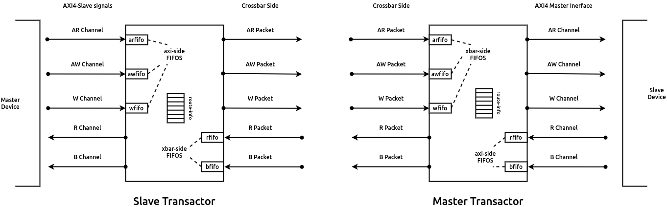
Fig. 2.1 Master and Slave Transactors used within the AXI4 Crossbar
The cross-bar internally instantiates M slave transactors and S
master transactors. These transactors provide an AXI4 interface on one side (driving the external
signals of the cross-bar) and a FIFO like interface on the other side.
The M slave transactors provide an AXI4
slave interface externally which are to be connected to M master devices like DMA masters, cache
masters, etc. The S master transactors provide an AXI4 master interface externally, which are to
be connected to slave devices like, UART, SPI, Memory controllers, etc.
Each of these transactors internally include a two entry FIFO on each of the five AXI4 channels. For the slave transactors, the FIFOs on the AW, W and AR channels are enqueued when the corresponding master devices drive valid transactions on these channels. We will refer to these set of FIFOs as axi-side FIFOs. The FIFOs on the R and B channels are enqued by logic within the interconnect and will be refered to as xbar-side FIFOs. The axi-side and xbar-side fifos for a master transactor are interchanged as compared to the slave transactor. Fig. 2.1 shows the interface signals and the placement of these FIFOs for the master and slave trasactors.
When a master device initiates a new trasaction on the AR, AW or W channels the corresponding axi-side FIFOs hold a valid entry for routing within the crossbar interconnect in the immediate cycle. Similarly, when the crossbar routes an R or B packet to the corresponding xbar-side FIFOs of the transactor, the master device will see these transactions in the immediate cycle. Fig. 2.2 shows the behavior in case of the AR channel being driven by a master device, and the corresponding axi-side FIFO in the connected slave transactor.

Fig. 2.2 Bevahvior of FIFO on the read-address channel of the slave transactor
Rest of the FIFOs in the slave transactor work analogously to the above behavior. The next section will discuss how transactions received on the axi-side FIFOs are routed to their destination through the crossbar.
2.2.3. Transaction Routing
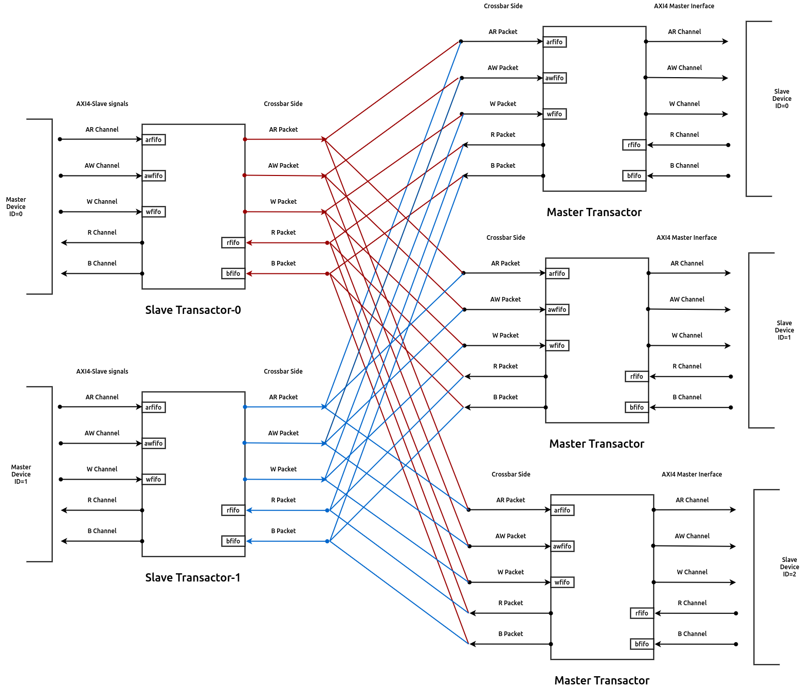
Fig. 2.3 Crossbar interconnect with transactors and master/slave devices
Once the transactions from the master/slave devices are latched into the corresponding axi-side FIFOs, they need to be routed through the crossbar to their target nodes. It should be noted here that the routing logic for the read bus (comprising of the AR and R channels/packets) is separate from the routing logic for the write bus (comprising of the AW, W and B channels/packets) to leverage maximum performance. The next paragraphs will discuss the routing for read and write transactions
- Read Transactions:
Once the arfifo in the slave transactors have a valid entry, the target master transactor to which this transaction needs to be routed is deduced using the
fn_rd_memory_mapfunction provided to the design at compile time. However, the salve transactor can only carry out the transfer to the master transactor, if the arfifo in the master transactor has atleast one empty slot.It is possible that the slave device connected to the master transactor is busy has not been able to service the pending request(s) that are present in arfifo thereby causing it to become full in due course of time. In such a scenario, a new request from a slave transactor can no longer be enqued and thus creates a stall. The slave transactor continues the attempt to make the transfer again in the sub-sequent cycles until success.
Note
Transactions sitting in any of the fifos in the transactors, like the case above, can be defined as in-flight transactions, which have been received by the master/slave device but have not yet reached the target slave/master device.
To keep track of the pending transactions generated by a slave transactor and where the response of master transactor should be routed to, the crossbar maintains a series of route-info FIFOs in the slave and master transactors. For the read transactions, each slave and master transactor include an 8-entry route-info FIFO to store the master and slave ids participating in a transaction. In a slave transactor, this FIFO indicates which slave-device’s (master transactor) response is expected to be routed to the connected master-device. Similarly, the route-info FIFO in a master transactor indicates the ID of the master-device (slave transactor) to whom the response is to be routed to.
Note
This implementation has a limitation of not supporting interleaving and data reordering, and thus slave-devices connected to this crossbar cannot have a re-ordering depth of more than 1. i.e. all responses from the particular slave device have to be in the same order of the requests presented at its port.
These route-info FIFOs are enqueued with the master/slave IDs when a valid transfer between a slave transactor ar-fifo and master transactor ar-fifo occurs.
Once the master transactor sends an RLAST signal on the R packet, the corresponding route-info FIFOs are popped (dequeued) allowing the slave/master to serve the next pending transaction in order.
Fig. 2.4 shows the above behavior of the read transaction routing happening between a master device with ID M1 and a slave device with ID S1.

Fig. 2.4 Read transaction routing through the crossbar.
- Write Transactions:
The working of the write transactions is very similar to that of the read transactions, except for the change that an extra set of route-info FIFOs are maintained on each master and slave transactor for the W channel as well. Thus each transactor maintains a route-info FIFO for the AW channel and another route-info for the W channel.
Therefore, when a valid transfer occurs between the aw-fifo of the slave transactor and the aw-fifo of the master transactor, the AW and W channel route-info FIFOs of both the transactors are updated. Ths W channel route-info FIFOs, ensure that the sub-sequent beats of the transaction from the slave transactor are routed to the correct master transactor.
The route-info FIFOs are popped/dequeued when the write response of the B channel is received. Fig. 2.5 shows the behavior of the write transactions through the crossbar.

Fig. 2.5 Write transaction routing through the crossbar.
2.2.4. Arbitration Policy
When multiple slave transactors select the same master-transactor to perform a similar type of
(read/write) transaction, arbitration is required to choose which slave transactor will succeed.
The implementation supports two types of arbitration policy: fixed and round-robin. At design time,
the user needs to define which slave-transactors will participate in fixed arbitration and which will
participate in round-robin arbitration using the fixed_priority_* parameters defined in
Table 2.2.
Note
Since the read and write channels operate independently, it is possible to have the read port of a master-device to have a fixed priority while the write port can participate in round-robin arbitration or vice-versa.
- Fixed Priority Arbitration:
- By default, the arbitration is granted based on the relative priority of the associated IDs of the slave transactors (refer to Section 2.2.1 for more details on how IDs are assigned). A slave transactor with a lower ID has higher priority over a slave transactor with a higher ID.
- Round-Robin Arbitration:
For round robin arbitration, the design maintains separate select registers for read and write port arbitration, whose reset value is 0. The select register indicates the threshold ID value. When a contention occurs, the participating slave transactor whose ID is immediately above the select register wins the arbitration. Once a slave transactor is chosen, the select register is updated by a value one greater than the ID of the winning transactor. In case the winning ID is the highest then the value assigned it 0.
It is possible, that any point there is a contention amongst slave transactors with fixed arbitration and slave transactors configured for round-robin arbitration. In such a case, the slave transactor with fixed arbitration having an ID lower than the ID of the slave transactor winning the round-robin arbitration is given access to the master transactor. If all the slave transactors with fixed arbitration have an ID higer than the slave transactor winning the round-robin arbitration, then the latter is given access to the master transactor.
Fig. 2.6 Shows how round robin arbitration would work for a crossbar consisting of 2 slave transactors with a select threshold of 1.

Fig. 2.6 Round Robin arbitration amongst 2 masters
2.2.5. Address Decode
The cross-bar module requires two functions (fn_rd_memory_map and
fn_wr_memory_map) to be
provided at design time which are used by the read and write channels to
identify a target slave-device. The functions should take as input an address of the
same width : wd_addr and return a slave-device id number which indicates which one of
the vectored slave interfaces have been selected for this transaction by the master device.
Disjoint address spaces selecting the same slave are also allowed. The distinction between these address spaces is the responsibility of the slave-device.
Note
If a device is read-only or write-only then its memory map allocation can be skipped
from the fn_rd_memory_map or fn_wr_memory_map functions respectively to remove the
corresponding channel connections.
2.2.6. Error signaling
The cross-bar does not internally generate the DECERR, but expects that one of
the S slaves is an Error Slave which is selected for all holes within
the address maps (applies to both read and write channels) and responds with a DECERR.
Tip
When defining the fn_wr_memory_map and fn_rd_memory_map functions, its recommended to
assign the error slave ID under last else condition of an if-else construct or under the
default condition of a case statement.
2.2.7. Instance Mapping in Verilog
The following provides a mapping between the data structures/elements mentioned above to instances/signals available in the generated Verilog.
Note
The following mapping assumes the instance name of the crossbar to be fabric.
- Route-Info FIFOs:
The route-info FIFO instances in the slave transactors are named:
fabric_f_s_rd_route_info_<num>fabric_f_s_wd_route_info_<num>fabric_f_s_wr_route_info_<num>
The route-info FIFO instances in the master transactors are named:
fabric_f_m_rd_route_info_<num>fabric_f_m_wd_route_info_<num>fabric_f_m_wr_route_info_<num>
<num> in the above strings should be replaced by the ID of the slave/master transactor assigned at design time.
- Channel FIFOs:
The various xbar-side and axi-side FIFOs within the slave transactors are named:
fabric_xactors_from_masters_<num>_f_arfifofabric_xactors_from_masters_<num>_f_awfifofabric_xactors_from_masters_<num>_f_wfifofabric_xactors_from_masters_<num>_f_rfifofabric_xactors_from_masters_<num>_f_bfifo
The various xbar-side and axi-side FIFOs within the master transactors are named:
fabric_xactors_to_slaves_<num>_f_arfifofabric_xactors_to_slaves_<num>_f_awfifofabric_xactors_to_slaves_<num>_f_wfifofabric_xactors_to_slaves_<num>_f_rfifofabric_xactors_to_slaves_<num>_f_bfifo
<num> in the above strings should be replaced by the ID of the slave/master transactor assigned at design time.
2.3. Using the Cross-bar IP
The IP is designed in BSV and available at: https://gitlab.com/incoresemi/blocks/fabrics . The following steps demonstrate on how to configure and generate verilog RTL of the cross-bar IP.
Note
The user is expected to have the downloaded and installed open-source bluespec compiler available at: https://github.com/BSVLang/Main
2.3.1. Configuration and Generation
Setup:
The IP uses the python based cogapp tool to generate bsv files with cofigured instances. Steps to install the required tools to generate the configured IP in verilog RTL can be found in Appendix. If you are using a python virtual environment make sure its activated before proceeding to the following steps.
Clone the repo:
git clone https://gitlab.com/incoresemi/blocks/fabrics.git
./manager.sh update_deps
cd axi4/test
Configure Design:
The yaml file:
axi4_crossbar_config.yamlis used for configuring the crossbar. Please refer to Table 2.1 for information on the parameters used in the yaml file.Address map should also be specified in this file using the slot-number as the key of the dictionary. Following rules apply to the memory map:
- Slot-numbering should be from 0 to
tn_num_slaves - 1 - Each slave can have one of the following access policies:
read-only,write-only,read-writeanderror. Anerrorslave need not have thebaseandboundfields specified. - Atleast one of the slaves should have access as
error - While providing the address based and bounds, remember the base is included and bound is not for the device under consideration
- Slot-numbering should be from 0 to
Generate Verilog: Use the following command with required settings to generate verilog for synthesis/simulation:
make TOP_FILE=axi4_crossbar.bsv TOP_MODULE=mkaxi4_crossbar generate_instances
The generated verilog file is available in:
build/hw/verilog/mkaxi4_crossbar.vInterface signals: In the generated verilog, the vectored slave interface signals (to which masters will be connected to) are prefixed with
frm_master_<num>. The vectored master interface signals (to which slaves will be connected to) are prefixed withto_slaves_<num>. Since the IP is a synchronous IP, the same clock and reset (active-low) signals (ACLKandARESETN) are used by all channles across all devices.Simulation: The top module for simulation is
mkaxi4_crossbar. Please follow the steps mentioned in Section 8.2 when compiling the top-module for simulation
2.3.2. Verilog Signals
Table 2.3 describes the signals in the generated verilog for the following configuration
wd_id: 4
wd_addr: 32
wd_data: 64
wd_user: 0
tn_num_masters: 1
tn_num_slaves:  1
fixed_priority_rd: 0b1
fixed_priority_wr: 0b1
memory_map:
  0:
    access: error
| Signal Names | Direction | Size(Bits) | Description |
| ACLK | Input | 1 | clock for all channels |
| ARESETN | Input | 1 | an active low reset |
| frm_master_0_AWREADY | Output | 1 | signal sent to master-device |
| frm_master_0_WREADY | Output | 1 | signal sent to master-device |
| frm_master_0_BVALID | Output | 1 | signal sent to master-device |
| frm_master_0_BID | Output | 4 | signal sent to master-device |
| frm_master_0_BRESP | Output | 2 | signal sent to master-device |
| frm_master_0_ARREADY | Output | 1 | signal sent to master-device |
| frm_master_0_RVALID | Output | 1 | signal sent to master-device |
| frm_master_0_RID | Output | 4 | signal sent to master-device |
| frm_master_0_RDATA | Output | 64 | signal sent to master-device |
| frm_master_0_RRESP | Output | 2 | signal sent to master-device |
| frm_master_0_RLAST | Output | 1 | signal sent to master-device |
| to_slave_0_AWVALID | Output | 1 | signal sent to slave-device |
| to_slave_0_AWID | Output | 4 | signal sent to slave-device |
| to_slave_0_AWADDR | Output | 32 | signal sent to slave-device |
| to_slave_0_AWLEN | Output | 8 | signal sent to slave-device |
| to_slave_0_AWSIZE | Output | 3 | signal sent to slave-device |
| to_slave_0_AWBURST | Output | 2 | signal sent to slave-device |
| to_slave_0_AWLOCK | Output | 1 | signal sent to slave-device |
| to_slave_0_AWCACHE | Output | 4 | signal sent to slave-device |
| to_slave_0_AWPROT | Output | 3 | signal sent to slave-device |
| to_slave_0_AWQOS | Output | 4 | signal sent to slave-device |
| to_slave_0_AWREGION | Output | 4 | signal sent to slave-device |
| to_slave_0_WVALID | Output | 1 | signal sent to slave-device |
| to_slave_0_WDATA | Output | 64 | signal sent to slave-device |
| to_slave_0_WSTRB | Output | 8 | signal sent to slave-device |
| to_slave_0_WLAST | Output | 1 | signal sent to slave-device |
| to_slave_0_BREADY | Output | 1 | signal sent to slave-device |
| to_slave_0_ARVALID | Output | 1 | signal sent to slave-device |
| to_slave_0_ARID | Output | 4 | signal sent to slave-device |
| to_slave_0_ARADDR | Output | 32 | signal sent to slave-device |
| to_slave_0_ARLEN | Output | 8 | signal sent to slave-device |
| to_slave_0_ARSIZE | Output | 3 | signal sent to slave-device |
| to_slave_0_ARBURST | Output | 2 | signal sent to slave-device |
| to_slave_0_ARLOCK | Output | 1 | signal sent to slave-device |
| to_slave_0_ARCACHE | Output | 4 | signal sent to slave-device |
| to_slave_0_ARPROT | Output | 3 | signal sent to slave-device |
| to_slave_0_ARQOS | Output | 4 | signal sent to slave-device |
| to_slave_0_ARREGION | Output | 4 | signal sent to slave-device |
| to_slave_0_RREADY | Output | 1 | signal sent to slave-device |
| frm_master_0_AWVALID | Input | 1 | signal driven by master-device |
| frm_master_0_AWID | Input | 4 | signal driven by master-device |
| frm_master_0_AWADDR | Input | 32 | signal driven by master-device |
| frm_master_0_AWLEN | Input | 8 | signal driven by master-device |
| frm_master_0_AWSIZE | Input | 3 | signal driven by master-device |
| frm_master_0_AWBURST | Input | 2 | signal driven by master-device |
| frm_master_0_AWLOCK | Input | 1 | signal driven by master-device |
| frm_master_0_AWCACHE | Input | 4 | signal driven by master-device |
| frm_master_0_AWPROT | Input | 3 | signal driven by master-device |
| frm_master_0_AWQOS | Input | 4 | signal driven by master-device |
| frm_master_0_AWREGION | Input | 4 | signal driven by master-device |
| frm_master_0_WVALID | Input | 1 | signal driven by master-device |
| frm_master_0_WDATA | Input | 64 | signal driven by master-device |
| frm_master_0_WSTRB | Input | 8 | signal driven by master-device |
| frm_master_0_WLAST | Input | 1 | signal driven by master-device |
| frm_master_0_BREADY | Input | 1 | signal driven by master-device |
| frm_master_0_ARVALID | Input | 1 | signal driven by master-device |
| frm_master_0_ARID | Input | 4 | signal driven by master-device |
| frm_master_0_ARADDR | Input | 32 | signal driven by master-device |
| frm_master_0_ARLEN | Input | 8 | signal driven by master-device |
| frm_master_0_ARSIZE | Input | 3 | signal driven by master-device |
| frm_master_0_ARBURST | Input | 2 | signal driven by master-device |
| frm_master_0_ARLOCK | Input | 1 | signal driven by master-device |
| frm_master_0_ARCACHE | Input | 4 | signal driven by master-device |
| frm_master_0_ARPROT | Input | 3 | signal driven by master-device |
| frm_master_0_ARQOS | Input | 4 | signal driven by master-device |
| frm_master_0_ARREGION | Input | 4 | signal driven by master-device |
| frm_master_0_RREADY | Input | 1 | signal driven by master-device |
| to_slave_0_AWREADY | Input | 1 | signal driven by slave-device |
| to_slave_0_WREADY | Input | 1 | signal driven by slave-device |
| to_slave_0_BVALID | Input | 1 | signal driven by slave-device |
| to_slave_0_BID | Input | 4 | signal driven by slave-device |
| to_slave_0_BRESP | Input | 2 | signal driven by slave-device |
| to_slave_0_ARREADY | Input | 1 | signal driven by slave-device |
| to_slave_0_RVALID | Input | 1 | signal driven by slave-device |
| to_slave_0_RID | Input | 4 | signal driven by slave-device |
| to_slave_0_RDATA | Input | 64 | signal driven by slave-device |
| to_slave_0_RRESP | Input | 2 | signal driven by slave-device |
| to_slave_0_RLAST | Input | 1 | signal driven by slave-device |