4. APB Interconnect
This interconnect supports the AMBA APB Protocol specification 2.0 (a.k.a APB4) The interconnect is used to connect a single APB compliant master device to one or more APB copmliant memory mapped slave devices.
In this chapter S would represent the number of slaves connected to the interconnect.
4.1. Parameters
Each instance of the interconnect consists of a single APB slave signals which should be connected to either master-transactors or directly to a master interface and vectored APB master signals which should be connected to either slave-transactors or directly to a slave interface.
The interconnect interfaces are parameterized with the following parameters:
| Parameter Name | Description |
wd_addr |
size of the address fields in the read-address and write-address channels |
wd_data |
size of the data fields in the read-response and write-data channels |
wd_user |
size of the user fields in all the channels. |
tn_num_slaves |
indicates the number of slaves that will be connected to this fabric. |
While the above parameters control the interface signals of the cross-bar, the following need to be provided to the module instance to control the arbitration and connection:
| Parameter Name | Description |
fn_addr_map |
A function which provides a memory map of the address-space. It takes an address as an argument and returns a one-hot S sized vector indicating which slave is selected for the transaction. |
4.2. Theory of Operation
The interconnect implementation is quite simple where, the address presented by the master is used to identify which slave is selected and thus the respective PSEL line is asserted to initiate the transaction. All other signals from the master are simply broad-cast to all the slaves.
Within the vectored master interfaces, all the signals are replicated. The respones from the slave devices is routed based on which slave’s PSEL is asserted.
4.2.1. Transactors
The library provides two transctors: master transactor and slave transactor. The master transactor has FIFO like interface on one side to receive request from the a master-device and generate the APB master signals on the other side. The slave transactor on the other hand has APB slave interface on one side to accept and respond to requests and a FIFO like interface on the other side to interact with the slave devices.
The master transactor (connected to the master-device externally) can be in one of the three modes: IDLE, SETUP or ACCESS. On reset the transactor is in IDLE mode, willing to accept a new request from the master-device. Operating Modes of the master transactor shows the various modes of operation of the master transactor amongst the mentioned modes.
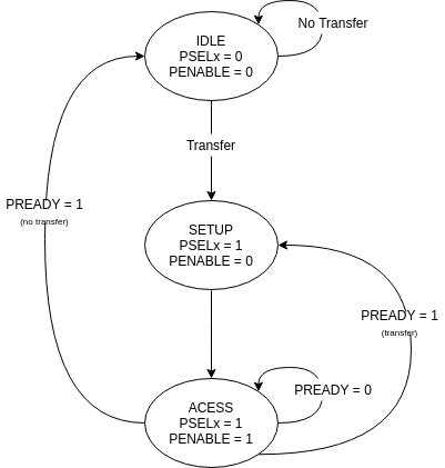
Fig. 4.1 Operating Modes of the master transactor
When a transfer is requested by the master-device, the transactor moves from IDLE mode to the SETUP mode and selects the appropriate slave by setting the corresponding PSELx signal. The next clock cycle, the transactor moves to the ACCESS mode, where PENABLE is asserted. The ACCESS mode is completed only when the PREADY signal from the selected slave is high. On completion of the ACCESS mode, if a new pending transaction is detected from the master-device, then the transactor moves to SETUP mode else goes back to the IDLE mode.
4.3. Using the Interconnect IP
The IP is designed in BSV and available at: https://gitlab.com/incoresemi/blocks/fabrics The following steps demonstrate on how to configure and generate verilog RTL of the cross-bar IP.
Note
The user is expected to have the downloaded and installed open-source bluespec compiler available at: https://github.com/BSVLang/Main
4.3.1. Configuration and Generation
Setup:
The IP uses the python based cogapp tool to generate bsv files with cofigured instances. Steps to install the required tools to generate the configured IP in verilog RTL can be found in Appendix. Python virtual environment needs to be activated before proceeding to the following steps.
Clone the repo:
git clone https://gitlab.com/incoresemi/blocks/fabrics.git
./manager.sh update_deps
cd apb/test
Configure Design:
The yaml file:
apb_interconnect_config.yamlis used for configuring the crossbar. Please refer to Table 4.1 for information on the parameters used in the yaml file.Address map should also be specified in this file using the slot-number as the key of the dictionary. Following rules apply to the memory map:
- slot-numbering should be from 0 to
tn_num_slaves - 1 - Each slave can have one of the following access policies:
read-only,write-only,read-writeanderror. Anerrorslave need not have thebaseandboundfields specified. - Atleast one of the slaves should have access as
error - While providing the address based and bounds, remember the base is included and bound is not for the device under consideration
- slot-numbering should be from 0 to
Generate Verilog: use the following command with required settings to generate verilog for synthesis/simulation:
make TOP_FILE=apb_interconnect.bsv TOP_MODULE=mkapb_interconnect generate_instances
The generated verilog file is available in:
build/hw/verilog/mkapb_interconnect.vInterface signals: in the generated verilog, the slave interface signals (to which the master device will be connected to) are prefixed with
frm_master_<num>. The vectored master interface signals (to which slave devices will be connected to) are prefixed withto_slaves_<num>. Since the IP is a synchronous IP, the same clock and reset (active-low) signals (PCLKandPRESETN) are used by all channles across all devices.
4.3.2. Verilog Signals
Table 4.3 describes the signals in the generated verilog for the following configuration
wd_addr: 32
wd_data: 64
wd_user: 0
tn_num_slaves:  1
memory_map:
  0:
    access: error
| Signal Names | Direction | Size(Bits) | Description |
| PCLK | Input | 1 | clock for all channels |
| PRESETN | Input | 1 | an active low reset |
| frm_master_PREADY | Output | 1 | signal sent to master |
| frm_master_PRDATA | Output | 32 | signal sent to master |
| frm_master_PSLVERR | Output | 1 | signal sent to master |
| v_to_slaves_0_PADDR | Output | 32 | signal sent to slave |
| v_to_slaves_0_PROT | Output | 3 | signal sent to slave |
| v_to_slaves_0_PENABLE | Output | 1 | signal sent to slave |
| v_to_slaves_0_PWRITE | Output | 1 | signal sent to slave |
| v_to_slaves_0_PWDATA | Output | 32 | signal sent to slave |
| v_to_slaves_0_PSTRB | Output | 4 | signal sent to slave |
| v_to_slaves_0_PSEL | Output | 1 | signal sent to slave |
| frm_master_PADDR | Input | 32 | signal driven by master |
| frm_master_PROT | Input | 3 | signal driven by master |
| frm_master_PENABLE | Input | 1 | signal driven by master |
| frm_master_PWRITE | Input | 1 | signal driven by master |
| frm_master_PWDATA | Input | 32 | signal driven by master |
| frm_master_PSTRB | Input | 4 | signal driven by master |
| frm_master_PSEL | Input | 1 | signal driven by master |
| v_to_slaves_0_PREADY | Input | 1 | signal driven by slave |
| v_to_slaves_0_PRDATA | Input | 32 | signal driven by slave |
| v_to_slaves_0_PSLVERR | Input | 1 | signal driven by slave |