3. AXI4-Lite Cross-bar Interconnect
The AXI4-Lite Cross-bar interconnect is used to connect one or more AXI4-Lite compliant master devices to one or more AXI4-Lite compliant slave devices. In includes the following features:
- The address widths can go upto 64-bits.
- The data widths supported are: 32, 64, 128, 256, 512 and 1024.
- Provides a configurable size of user-space on each channel.
- Supports aligned and unaligned transfers.
- Support read-only and write-only master-slave combinations resulting in reduced overheads.
- Static and Round Robin priority arbitration
From henceforth, M would represent the number of masters connected to the
cross-bar and S would represent the number of slaves connected to the
cross-bar.
3.1. Parameters
Each instance of the cross-bar consists of vectored AXI4-Lite slave signals which are connected to either master-transactors or directly to a master interface and vectored AXI4-Lite master signals which are connected to either slave-transactors or directly to a slave interface.
The cross-bar interfaces are parameterized with the following parameters:
| Parameter Name | Description |
wd_addr |
size of the address fields in the read-address and write-address channels |
wd_data |
size of the data fields in the read-response and write-data channels |
wd_user |
size of the user fields in all the channels. |
tn_num_masters |
indicates the number of masters that will be connected to this fabric. |
tn_num_slaves |
indicates the number of slaves that will be connected to this fabric. |
While the above parameters control the interface signals of the cross-bar, the following need to be provided to the module instance to control the arbitration and connection:
| Parameter Name | Description |
fn_rd_memory_map |
A function which provides a memory map of the address-space. It takes an address as an argument and returns a slave-number. This function is used by the read channels. |
fn_wr_memory_map |
A function which provides a memory map of the address-space. It takes an address as an argument and returns a slave-number. This function is used by the write channels. |
read_slave |
An S sized mask vector indicating if a particular slave has read support
or not |
write_slave |
An S sized mask vector indicating if a particular slave has write support
or not |
fixed_priority_rd |
An M sized vector which indicates if the respective master has fixed
priority of participates in round-robin arbitration on the read channel.
Setting a bit to 1 indicates the master as fixed priority, while setting it
to 0 would mean it participates in round-robin arbitration with other masters
who has their bits set to 0. |
fixed_priority_wr |
An M sized vector which indicates if the respective master has fixed
priority of participates in round-robin arbitration on the write channel.
Setting a bit to 1 indicates the master as fixed priority, while setting it
to 0 would mean it participates in round-robin arbitration with other masters
who has their bits set to 0. |
Note
By using the above two functions, one can generate an area optimized cross-bar for a given SoC which may contain read-only and write-only slaves.
Note
It is recommended to keep the masters participating in round-robin to be contiguous (either at the LSBs or the MSBs) for consistent fairness. More details on arbitration policy are available in Arbitration Policy
3.2. Micro-Architecture
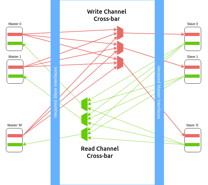
Fig. 3.1 Crossbar Data Paths for Read and Write Channels
The cross-bar internally instantiates M slave transactors and the S
master transactors. The slave transactors recieve signals from the M masters
connected to the cross-bar, while the master transactors recieve signals from
the S slaves connected to the cross-bar.
As shown in Fig. 3.1 the arbitration logic for the read and write channels are
maintained separately to enable maximum parallelism. The cross bar also
implements two M x S matrices which keep track of the transaction
originated between masters and slaves and thus guide in routing the responses
from the slaves to the masters.
Each element in the above connection matrices is an 8 entry fifo structure,
thereby allowing to queue upto 8 unique requests between the master-slave
combination.
The cross-bar implements parallel read and write data paths connecting each slave interface to all master interfaces it can access based on the memory map functions provided. At any point multiple transactions from different sources to different destinations can occur within the cross-bar.
3.2.1. Arbitration Policy
By default, the arbitration is granted based on the relative priority of the associated masters connected to the vectored slave interace. A master connected to a lower slot number on the vectored interface has higher priority over a master connected to a higher slot number.
However, during instantiation one can choose which masters should participate in a round-robin arbitration scheme for read and write channels by using the parameters mentioned in Parameters.
3.2.2. Address Decode
The cross-bar module requires two functions (fn_rd_memory_map and
fn_wr_memory_map) to be
provided as an input which is used by the read and write channels to
identify a correct-slave. The function should take as input an address of the
same width : wd_addr and return a slave-number which indicates which one of
the vectored slave interfaces has been selected for this transaction.
Disjoint address spaces selecting the same slave are also allowed. The distinction between these address spaces is the responsibility of the slave device.
If a device is read-only or write-only then its memory map allocation can be skipped
from the fn_rd_memory_map or fn_wr_memory_map functions respectively to remove the
corresponding channel connections.
3.2.3. Error signaling
The cross-bar does not internally generate the DECERR, it expected that one of
the S slaves is an Error Slave which is selected for all holes within
the address maps (applies to both read and write channels) and responds with a DECERR.
3.3. Using the Cross-bar IP
The IP is designed in BSV and available at: https://gitlab.com/incoresemi/blocks/fabrics The following steps demonstrate on how to configure and generate verilog RTL of the cross-bar IP.
Note
The user is expected to have the downloaded and installed open-source bluespec compiler available at: https://github.com/BSVLang/Main
3.3.1. Configuration and Generation
Setup:
The IP uses the python based cogapp tool to generate bsv files with cofigured instances. Steps to install the required tools to generate the configured IP in verilog RTL can be found in Appendix. Python virtual environment needs to be activated before proceeding to the following steps.
Clone the repo:
git clone https://gitlab.com/incoresemi/blocks/fabrics.git
./manager.sh update_deps
cd axi4/test
Configure Design:
The yaml file:
axi4l_crossbar_config.yamlis used for configuring the crossbar. Please refer to Table 2.1 for information on the parameters used in the yaml file.Address map should also be specified in this file using the slot-number as the key of the dictionary. Following rules apply to the memory map:
- slot-numbering should be from 0 to
tn_num_slaves - 1 - Each slave can have one of the following access policies:
read-only,write-only,read-writeanderror. Anerrorslave need not have thebaseandboundfields specified. - Atleast one of the slaves should have access as
error
- slot-numbering should be from 0 to
Generate Verilog: use the following command with required settings to generate verilog for synthesis/simulation:
make TOP_FILE=axi4l_crossbar.bsv TOP_MODULE=mkaxi4l_crossbar generate_instances
The generated verilog file is available in:
build/hw/verilog/mkaxi4l_crossbar.vInterface signals: in the generated verilog, the vectored slave interface signals (to which masters will be connected to) are prefixed with
frm_master_<num>. The vectored master interface signals (to which slaves will be connected to) are prefixed withto_slaves_<num>. Since the IP is a synchronous IP, the same clock and reset (active-low) signals (ACLKandARESETN) are used by all channles across all devices.Simulation: The top module for simulation is
mkaxi4l_crossbar. Please follow the steps mentioned in Section 8.2 when compiling the top-module for simulation
3.3.2. Verilog Signals
Table 3.3 describes the signals in the generated verilog for the following configuration
wd_addr: 32
wd_data: 64
wd_user: 0
tn_num_masters: 1
tn_num_slaves:  1
fixed_priority_rd: 0b1
fixed_priority_wr: 0b1
memory_map:
  0:
    access: error
| Signal Names | Direction | Size(Bits) | Description |
| ACLK | Input | 1 | clock for all channels |
| ARESETN | Input | 1 | an active low reset |
| frm_master_0_AWREADY | Output | 1 | signal sent to master |
| frm_master_0_WREADY | Output | 1 | signal sent to master |
| frm_master_0_BVALID | Output | 1 | signal sent to master |
| frm_master_0_BRESP | Output | 2 | signal sent to master |
| frm_master_0_ARREADY | Output | 1 | signal sent to master |
| frm_master_0_RVALID | Output | 1 | signal sent to master |
| frm_master_0_RDATA | Output | 64 | signal sent to master |
| frm_master_0_RRESP | Output | 2 | signal sent to master |
| to_slave_0_AWVALID | Output | 1 | signal sent to slave |
| to_slave_0_AWADDR | Output | 32 | signal sent to slave |
| to_slave_0_AWPROT | Output | 3 | signal sent to slave |
| to_slave_0_WVALID | Output | 1 | signal sent to slave |
| to_slave_0_WDATA | Output | 64 | signal sent to slave |
| to_slave_0_WSTRB | Output | 8 | signal sent to slave |
| to_slave_0_BREADY | Output | 1 | signal sent to slave |
| to_slave_0_ARVALID | Output | 1 | signal sent to slave |
| to_slave_0_ARADDR | Output | 32 | signal sent to slave |
| to_slave_0_ARPROT | Output | 3 | signal sent to slave |
| to_slave_0_ARREADY | Output | 1 | signal sent to slave |
| frm_master_0_AWVALID | Input | 1 | signal driven by master |
| frm_master_0_AWADDR | Input | 32 | signal driven by master |
| frm_master_0_AWPROT | Input | 3 | signal driven by master |
| frm_master_0_WVALID | Input | 1 | signal driven by master |
| frm_master_0_WDATA | Input | 64 | signal driven by master |
| frm_master_0_WSTRB | Input | 8 | signal driven by master |
| frm_master_0_BREADY | Input | 1 | signal driven by master |
| frm_master_0_ARVALID | Input | 1 | signal driven by master |
| frm_master_0_ARADDR | Input | 32 | signal driven by master |
| frm_master_0_ARPROT | Input | 3 | signal driven by master |
| frm_master_0_RREADY | Input | 1 | signal driven by master |
| to_slave_0_AWREADY | Input | 1 | signal driven by slave |
| to_slave_0_WREADY | Input | 1 | signal driven by slave |
| to_slave_0_BVALID | Input | 1 | signal driven by slave |
| to_slave_0_BRESP | Input | 2 | signal driven by slave |
| to_slave_0_ARREADY | Input | 1 | signal driven by slave |
| to_slave_0_RVALID | Input | 1 | signal driven by slave |
| to_slave_0_RDATA | Input | 64 | signal driven by slave |
| to_slave_0_RRESP | Input | 2 | signal driven by slave |